By Lauren Nagel
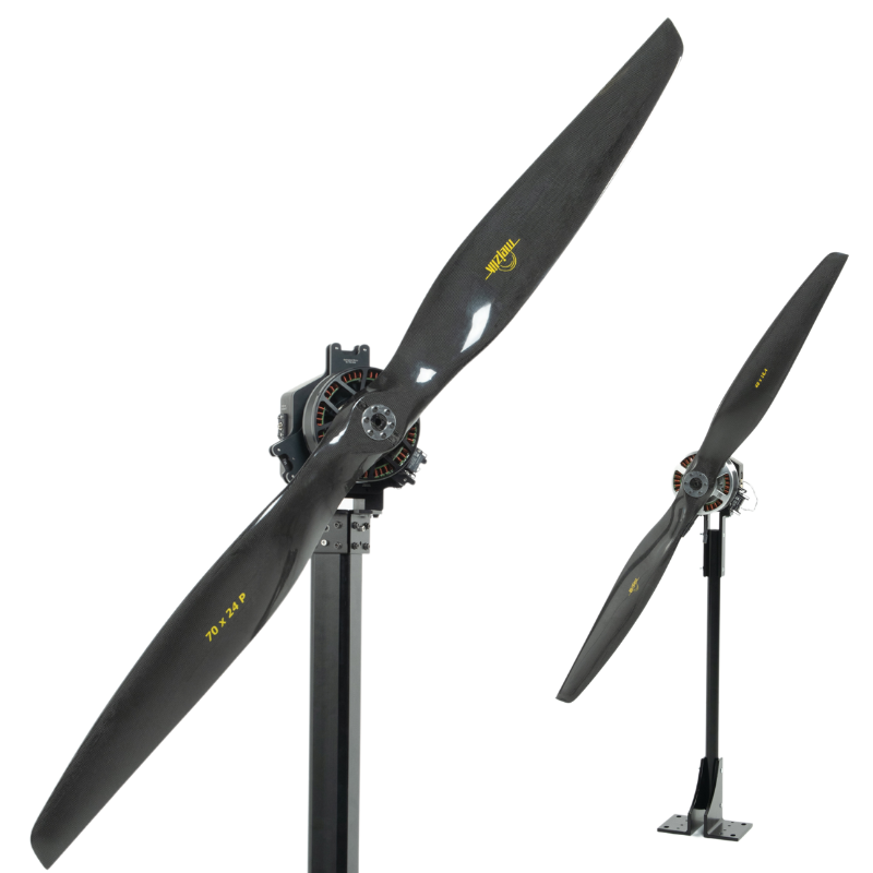
Propeller balancing is a critical process in ensuring the smooth operation, reliability, and longevity of UAVs (Unmanned Aerial Vehicles). The imbalance of a propeller can lead to vibration, noise, and accelerated wear on essential components, which can negatively impact flight performance.
The ISO 21940-11:2016 standard provides a widely referenced framework for rotor balancing, defining permissible levels of imbalance to achieve optimal rotor performance.
This article explores the key concepts behind the ISO 21940-11:2016 standard, the methods used to determine balance quality, and next steps for how UAV propellers can be balanced.
Table of Contents
-
ISO Rotor Balancing Standard
-
Methods to Determine Permissible Residual Imbalance
-
Summary Table of Balancing Grades
-
Next Steps
Click these links to learn how imbalanced propellers cause excess vibration and increased noise in drones.

1. ISO Rotor Balancing Standard
The most referenced standard for propeller balancing is ISO 21940-11:2016, “Procedures and tolerances for rotors with rigid behaviour”. It replaces the previous standard, 1940:1-2003, with updated definitions and wider applications.
The new standard, established in 2016, follows a simple premise: the level of imbalance (U) in a rotor is considered acceptable when the residual imbalance, U, is less than or equal to a pre-defined permissible residual imbalance, Uper is defined as the total tolerance in the plane of the centre of mass and is proportional to the mass of the rotor:

It is measured in kg·m (kilogram metres), g·mm (gram millimetres), kg·mm (kilogram millimetres) or mg·mm (milligram millimetres).
The ratio of Uper to rotor mass is called eper, defined as the permissible residual specific imbalance:
It is measured in is kg·m/kg (kilogram metres per kilogram), m (metres), g·mm/kg (gram millimetres per kilogram), or μm (micrometres), which is often the preferred unit as many eper values fall between 0,1 μm and 10 μm.
For a rotor with only a resultant imbalance (and a negligible moment imbalance), eper is the distance between the rotor’s centre of mass and the shaft axis.It has been observed that eper typically varies inversely with the service speed,n, of the rotor:

For UAV rotor balancing, one could swap ‘service speed’ with ‘cruise rotation speed’, the RPM at which the propeller operates during cruise flight.
This relationship can also be expressed as:

where
Ω = the angular velocity of the cruise speed, in rad/s
c is a constant
Differently put, 
wheren = cruise rotation speed in revolutions/minute.
2. Methods to Determine Permissible Residual Imbalance
ISO 21940-11:2016 specifies five methods that can be used to determine the magnitude of permissible residual imbalance:-
Balance quality grades, derived from long-term practical experience with a large number of different rotors
-
Experimental evaluation of permissible residual imbalances
-
Limited bearing forces due to imbalance
-
Limited vibrations due to imbalance
-
Established experience with imbalance tolerances
Methods 2 and 5 are most commonly employed by organisations that have amassed a significant amount of balancing data for their specific rotors, sufficient to internally set balance quality tolerances.
Method 1 employs a global standard based on “worldwide experience and similarity considerations” to set balance quality requirements for typical machinery types.The unit for balance quality grade according to method 1 is “G”, equivalent to the magnitude of eperΩexpressed in mm/s (millimetres per second). For example, if eperΩ = 6.3 mm/s, then the balance quality grade = G 6.3.
3. Summary Table of Balance Quality Grades
|
Machinery Types: general examples |
Balance quality grade (G) |
Magnitude (eperΩ mm/s) |
|
Crankshaft drives for large, slow marine diesel engines, inherently balanced |
G 1600 |
1600 |
|
Cars: wheels, wheel rims, drive shafts |
G 40 |
40 |
|
Aircraft gas turbine |
G 6.3 |
6.3 |
|
Electric motors of shaft height ≥80 mm |
G 2.5 |
2.5 |
|
Gyroscopes |
G 0.4 |
0.4 |
UAV propellers are typically balanced to a G 6.3 quality grade, ensuring low vibration levels and smooth operation. This minimizes strain on components, preventing excessive wear and avoiding interference with sensor performance.
4. Next Steps
We hope that this article has been informative. If you have any more questions about propeller balancing standards, let us know in the comments.
To learn more about propeller balancing best practices, check out our in-depth White Paper on Propeller Balancing Techniques.
If you’re ready to start balancing your propellers, check out ourDynamic Propeller Balancing Equipment.


 Back to Blog


Leave a comment